Pumps The accuracy of mechanical seal installation machine has a great influence on the amount of leakage in mechanical seal performance. Generally, the industrial pump (speed ≤ 3600r/min) is taken as an example, and the allowable values are introduced as follows.
1. Radial runout of shaft
Take the stationary seal box as the benchmark for measuring the radial runout of the shaft, as shown in Figure 11-1. Fix the dial indicator on the end face of the seal box as close as possible to the end face, and measure the radial runout of the shaft. The radial runout value is the value of the dial indicator that reads the rotation of the shaft for 1 cycle, showing the difference between the large and small values.
The radial runout of the shaft shall be within √ d/120mm.
2. Perpendicularity
The perpendicularity between the stationary shaft and the end face of the seal box is shown in Figure 11-2. Fix a dial indicator on the shaft and measure the value at the inner diameter of the end face of the seal box nearest to the gauge seat. The value of perpendicularity is the difference between the large and small numbers read on the dial indicator when the shaft rotates for 1 cycle.
Examples of industrial pumps shall conform to √ d/150mm or less.

3. Coaxiality
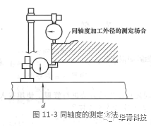
As shown in Figure 11-3, the coaxiality between the stationary shaft and the inner diameter of the seal box is measured by fixing the dial indicator on the shaft. At this time, install the dial indicator on the bracket near the left end as close as possible to the end face. In addition, the coaxiality value of the outer diameter can also be measured during processing. When the shaft rotates for one circle, the dial indicator reads the difference between the large and small values. Industrial pumps shall conform to 0.002 * dmm.

4. Shaft movement
The clearance between the bearings at rest determines the displacement of the shaft, as shown in Figure 11-4. Install a dial indicator on the shaft to measure the displacement relative to the end face of the seal box. The displacement value of the shaft is the difference between the large and small values of the dial indicator when reading the displacement of the shaft.
In the example of industrial pump, because the clearance of the bearing shaft displacement is specified to be below 0.2mm, and it rotates in one direction during normal continuous operation, it is considered that there is no displacement. Only when it is started, there will be intense displacement, which is also required to be below 0.2mm. In addition, in order to avoid the slow and relative extension of the rotating shaft due to overheating during operation, all axial displacement values should be less than 1mm.

5. Allowable values of dimensional tolerance and surface roughness
During the installation of mechanical seal, as shown in Figure 11-5, the allowable value of installation dimension tolerance and surface roughness of static ring installation position P, shaft seal ring installation position and other positions are very important.
In the case of industrial pumps, it is specified that the dimensional tolerance of the installation position P of the stationary ring is above the matching accuracy H7, and the installation position of the seal ring is above the level h7. In addition, the surface roughness at P, Q and R is different due to different materials of secondary seals, as shown in Table 11-5.

6. Accuracy requirements for machine operation
It is not enough to only pay attention to the accuracy of the machine when it is stationary, because the machine sometimes cannot maintain its original accuracy when it is running. The reasons for this are:
(1) Relative displacement caused by thermal expansion difference between casing and shaft caused by fluid or machine operation.
(2) The deformation of the machine itself is caused by the expansion and contraction of the piping.
(3) Casing deformation caused by pressure.
(4) The cavitation phenomenon occurs due to the reduction of machine efficiency or the increase of liquid vapor pressure, which in turn causes the vibration of various parts of the machine.
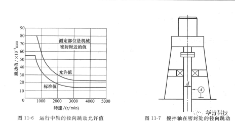
(5) The movement and vibration of the shaft are caused by the pressure fluctuation caused by the imbalance of liquid flow. In view of the above situation, the machine should also be checked and readjusted when it is running. The allowable radial runout of the shaft is given in Figure 11-6 as a reference.

Mixing transmission equipment (reaction kettle)
Mixing transmission equipment consists of transmission equipment (including motor, coupling, reducer, transmission shaft, support, mixing shaft, paddle blade), shaft seal and other parts. With reference to the technical documents of imported mixing transmission equipment, there are mainly the following requirements.
(1) The radial runout of the mixing shaft at the seal shall meet the following requirements (see Figure 11-7 and Table 11-6).

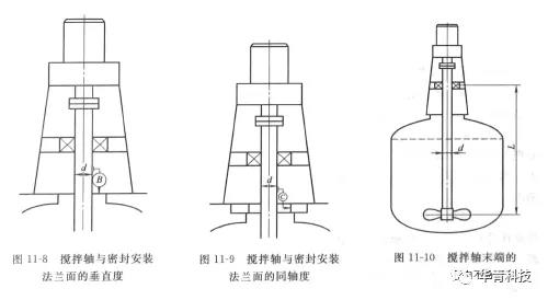
(2) The perpendicularity between the mixing shaft and the sealing installation flange surface shall meet the following requirements (see Figure 11-8 and Table 11-7).

(3) The coaxiality between the mixing shaft and the seal mounting flange surface shall meet the following requirements (see Figure 11-9 and Table 11-8).

(4) The radial runout of the end of the mixing shaft shall be ≤ (√ d+√ L)/200mm (see Figure 11-10).


