Purposes of flushing scheme for mechanical seals
Direct injection of liquid into the high-pressure side of double or single seal is called "flushing". Generally, pumps shall be flushed, especially light hydrocarbon pumps.
1. Flush to dissipate heat. Control the heat generated by the liquid seal. This can be achieved by flushing the seal chamber with liquid to take away heat and control the temperature rise.
2. Lower the liquid temperature. In some cases, the liquid temperature is too high to affect the sealing performance. In such cases, lower the temperature to improve the performance of the liquid.
3. Change the pressure of the seal chamber. In some cases, the seal chamber pressure needs to be increased or decreased to improve performance. This can be achieved by evaporation or by reducing the heat load on the seals.
4. Clean process fluid. If the process fluid contains unsuitable solid particles or contaminants, the fluid in the seal cavity needs to be cleaned. It may also be necessary to provide clean fluid from outside the sealing system.
5. Control the atmospheric side of the seal. Process liquids may dry, crystallize, or coke as they come into contact with the atmosphere. It is very important to prevent interaction with the atmosphere so as not to adversely affect the sealing performance.
Classification of mechanical seal flushing schemes
Single Seals
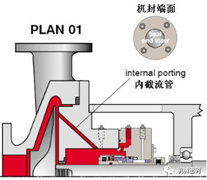
PLAN 01 (Single end self flushing)
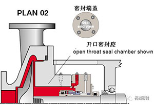
PLAN 02 (jacket cooling and heat tracing)
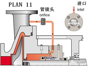
PLAN 11 (self flushing)
PLAN 13 (back flushing)
PLAN 14 (forward+reverse flushing)
PLAN 21 (self flushing with cooling)
PLAN 23 (internal flushing with circulating sleeve)
PLAN 31 (self flushing with suspension separator)
PLAN 32 (external flushing)
PLAN 41 (self flushing with suspension separator and heat exchanger)
Dual Seals
PLAN 52 (series seal with non pressure buffer tank)
PLAN 53A (double face seal with pressure sealing fluid)
PLAN 53B (double face seal of forced circulation sealing fluid)
PLAN 53C (double face seal with booster tank)
PLAN 54 (double face seal with external sealing fluid)
Quench Seals
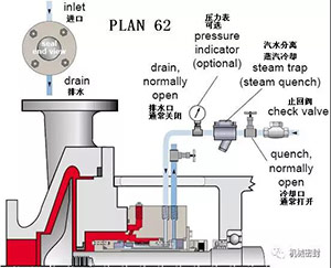
PLAN 62 (external flushing or quenching to prevent solid particles from accumulating on the sealing surface)
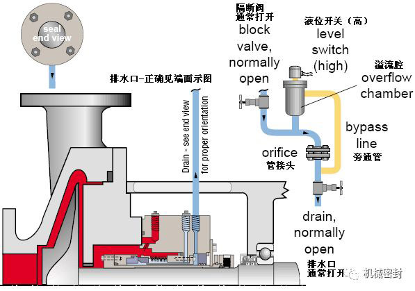
PLAN 65 (with float level switch to measure seal leakage)
Gas Seals
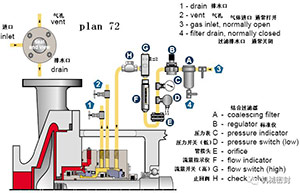
PLAN 72 (using isolated nitrogen for series dry gas seal of volatile medium)
PLAN 74 (double face dry gas seal)
PLAN 75 (for series dry gas seal of non-volatile medium)
PLAN 76 (series dry gas seal with external sealing gas)
Detailed diagrams of each scheme are as follows
1. Flushing scheme
Scheme:
Flush the inner mechanical seal chamber from the outlet end of the pump. Operation similar scheme PLAN11
reason:
The sealing chamber is cooled, and the sealing chamber of the horizontal pump is vented to prevent the freezing of the exposed pipes and the danger of fluid crystal blockage in PLAN 11 scheme
Occasion:
Ordinary seal chamber, possibly ANSI/ASME pump, is used for cleaning normal temperature fluid, which is used for single face seal and rarely for double face seal.
maintain:
The sealing surface shall not be directly flushed by flushing, and the mechanical seal shall not be excessively cooled. The flushing flow shall be calculated according to the head loss through the internal interceptor.
2. Flushing scheme
Scheme:
Closed sealing chamber without flushing.
reason:
No secondary circulation of fluid is required. Application: large hole/open sealing chamber under normal temperature operation, cooling jacket sealing chamber under high temperature operation, clean fluid, dry sealed vertical/jacking mixer/agitator,
maintain:
The process has enough critical space of boiling point to avoid vaporization. Under the condition of hot operation, there may always be cooling liquid in the seal chamber sleeve. The horizontal equipment must be able to exhaust by itself, and it is often used together with the cooling scheme PLAN62.
3. Flushing scheme
Scheme:
The mechanical seal flushing is carried out from the pump outlet through the flow limiting orifice plate, which violates the flushing scheme of single end mechanical seal.
Reason:
The cooling of the sealing chamber and the exhaust of the horizontal sealing chamber increase the pressure of the sealing chamber and the critical space for fluid vaporization.
Occasion:
Usually used for clean fluids, clean, non polymeric fluids.
maintain:
Use a flow limiting orifice with a bore diameter of 0.125 inches to calculate the flow rate to determine the size of the flow limiting orifice that will allow sufficient flow in the mechanical seal chamber. Determine the critical range for increasing the boiling point by using the appropriate size of the flow limiting orifice and throat bushing. The pipeline will flush the machine cover at 12 o'clock. Typical faults occur. The flow limiting orifice is blocked. Check the temperature at the end of the pipe.
4. Flushing scheme
Scheme:
The secondary circulation from the seal chamber to the pump inlet through the flow limiting orifice plate is the standard flushing scheme for vertical pumps.
reason:
Continuous exhaust of vertical pump seal chamber, and heat removal of seal chamber.
Occasion:
Vertical pump, seal chamber pressure is greater than the inlet pressure, mixed with medium sized solid normal temperature fluid, non polymer fluid.
maintain:
Before starting the vertical pump, bend the exhaust outlet pipeline, use the flow limiting orifice with a diameter of 0.125 inch, calculate the flow, to determine the size of the flow limiting orifice to ensure sufficient flow in the mechanical seal chamber, and reduce the pressure in the seal chamber by determining the size of the appropriate flow limiting orifice and throat bushing. Typical faults, the flow limiting orifice is blocked, and check the temperature at the end of the pipe.
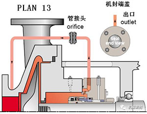
5. Flushing scheme
Scheme:
Flush the mechanical seal from the outlet of the pump and recycle it to the inlet of the pump with a flow limiting orifice. Combination of options 11 and 13.
reason:
Continuous exhaust of seal chamber of vertical pump, heat removal of seal chamber, increase the pressure of seal chamber and critical space of fluid vaporization.
Occasion:
Vertical pump, normal temperature, clean non polymer fluid.
maintain:
Use a flow limiting orifice with a diameter of 0.125 inch to calculate the flow to determine the size of the flow limiting orifice that will allow sufficient flow in the mechanical seal chamber. Determine the critical range of increasing boiling point through the appropriate size of the flow limiting orifice and throat bushing. Flush the sealing surface. Bend the exhaust pipe before starting the vertical pump. Typical fault, the flow limiting orifice is blocked, check the temperature at the end of the pipe.
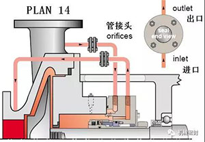
6. Flushing scheme
Scheme:
Flush the mechanical seal from the pump outlet through the flow limiting orifice plate and cooler, and add it to the cooler in Scheme 11, which increases the heat removal capacity.
reason:
Mechanical seal cooling, reduce fluid temperature, increase fluid and reduce coking
Occasion:
High temperature, hot water below 350 ° F (177 ° C) and above 180 ° F (80 ° C), clean, non polymer.
maintain:
The mechanical seal cooler or pipeline has air holes at high position, which shall be opened before startup. When the 682 mechanical seal cooler is used, the serial flow pipeline maximizes the heat transfer. Use a flow limiting orifice with a diameter of 0.125 inch to calculate the flow rate to determine the size of the flow limiting orifice that allows sufficient flow in the mechanical seal chamber. Determine the critical range for increasing the boiling point through the appropriate size of the flow limiting orifice and throat bushing. Frequently observe the inlet and outlet temperatures of the cooler to see if there is any sign of blockage or dirt deposition.
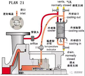
7. Flushing scheme
Scheme:
The circulation process of flushing the mechanical seal from the infusion ring in the sealing chamber through the cooler back to the sealing chamber, and the standard flushing scheme under hot water conditions.
reason:
Only by cooling a small part of liquid, the machine seal cooling under low load of the cooler can increase the critical range of fluid vaporization and improve the lubrication force of water.
Occasion:
Hot hydrocarbons at high temperatures, boiler feed water and hot water above 180 ° F (80 ° C), clean, non polymeric fluids.
maintain:
The mechanical seal cooler or pipeline has air holes at high position, which shall be opened before startup. When 682 mechanical seal cooler is used, the laminar flow pipeline makes the head loss smaller. The throat bushing clearance of the seal chamber is required to be very small to isolate the fluid. The plug of the peripheral seal cover should enter from the bottom and exit from the top. Frequently observe the inlet and outlet temperatures of the cooler to see if there is any sign of blockage or dirt deposition. The fluid containing iron should first flow through the iron remover and then into the cooler.
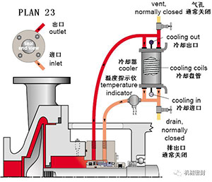
8. Flushing scheme
Scheme:
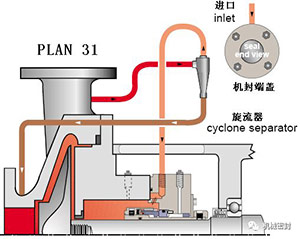
From the pump outlet, the machine seal is washed by the clean liquid of the hydrocyclone, and the centrifugally separated solids are sent to the pump inlet.
reason:
The mechanical seal cavity is de heated, and solids are removed from the flushing and sealing cavities.
Occasion:
Dirty or contaminated fluid or water with sand or pipe slag, non polymeric fluid.
maintain:
The specific gravity handled by the hydrocyclone is twice that of the fluid, and the pressure of the seal chamber is close to or equal to the inlet pressure to ensure moderate flow. The pipe should not include a flow limiting orifice plate (public number: pump manager). The sealing chamber does not have an exhaust hole. Typical fault: the cyclone or pipeline is blocked. Check the temperature at the end of the pipe.
9. Flushing scheme
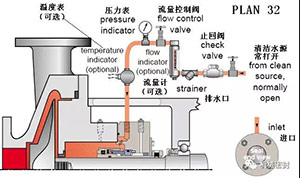
Scheme:
Flush the mechanical seal with an external cleaning source, and carefully select the source of flushing fluid to eliminate evaporation of injected liquid or contamination of pumped liquid.
reason:
The heat removal of the sealing chamber removes the process fluid or solid from the sealing chamber, increasing the pressure of the sealing chamber and the critical range of fluid vaporization.
Occasion:
Dirty or contaminated fluids, pulp, high temperature conditions, polymer or oxidizing fluids.
maintain:
The throat bushing with a certain size is used to maintain the pressure or maintain the fluid speed, limit the dirty process fluid, control the injection flow, increase the critical range of fluid vaporization, control the injection pressure, the injection fluid is compatible with the process fluid, and frequently observe the control system to check whether the valve is closed and blocked.
10. Flushing scheme
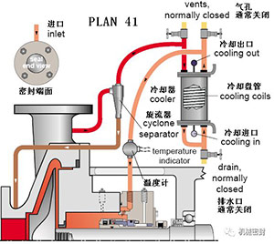
Scheme:
Clean liquid is sent from the pump outlet to the cooler through the hydrocyclone to flush the mechanical seal, and solids are sent to the pump inlet,
reason:
Seal cooling, flushing and solid removal from the seal chamber.
Occasion:
High temperature conditions, boiler feed water and hot water below 355 ° F (177 ° C), dirty or contaminated fluid and water with sand or pipe slag, non polymeric fluid.
maintain:
The mechanical seal cooler or pipeline has air holes at high position, which shall be opened before startup. When 682 mechanical seal cooler is used, the serial flow pipeline makes the heat transfer greater. The specific gravity handled by the hydrocyclone is twice that of the fluid, and the pressure of the seal chamber is close to or equal to the inlet pressure to ensure moderate flow. Typical fault: the cyclone or pipeline is blocked, check the temperature at the end of the pipe.
11. Flushing scheme
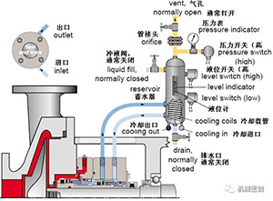
Scheme:
The external liquid storage tank provides buffer solution for the configuration of external seal. During normal operation, the internal infusion environment keeps circulating, and the liquid storage tank continuously discharges steam to the steam recovery system, and keeps the pressure lower than that of the seal chamber.
reason:
The external mechanical seal is the main seal, with little or no process emissions, and process pollution is not allowed.
Occasion:
It is used for double end face non pressure seal (series), high vapor pressure fluid, light hydrocarbon, dangerous/toxic fluid and heat transfer fluid.
maintain:
The pipe network has its own opening for the steam recovery/spark system that is close to the atmospheric pressure. The process steam pressure is usually greater than the pressure of the liquid storage tank. The buffer fluid is compatible with the process leakage fluid. The increased pore pressure will indicate the leakage of the main seal, and the liquid level gauge of the liquid storage tank will show the leakage of the external mechanical seal.
12. Flushing scheme
Scheme:
The external pressurized spacer tank provides clean liquid to the sealing chamber, and the circulation is completed by the internal infusion ring. The pressure of the spacer tank is greater than the pressure of the process fluid being sealed.
Reason:
Isolate process fluid and zero process discharge.
Occasion:
It is applicable to double face pressure seal (double), high vapor pressure fluid, light hydrocarbon, dangerous/toxic fluid, heat transfer fluid, dirty, corrosive and polymeric fluid, mixer/agitator and vacuum conditions.
maintain:
The pipe network has its own opening for the liquid storage tank at high position. Always pressurize the liquid storage tank. The gas pressure is allowed to be 150-200PSI (10-14bar). The barrier fluid is compatible with the process fluid. The liquid level gauge of the liquid storage tank shows the leakage of the inner and outer seals.
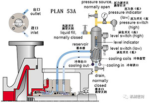
13. Flushing scheme
Scheme:
The external pipeline system provides liquid for the external seal of the pressurized double end face seal device, and the pressurized air bag accumulator provides pressure to the circulation system. The flow is maintained by the internal infusion ring, and the heat in the circulation system is removed by the air cooling or water cooling heat exchanger.
Reason:
Separation of process fluid, zero process discharge, higher pressure than 53A scheme.
Occasion:
It is applied to double end pressure seal (double), high vapor pressure fluid, light hydrocarbon, dangerous/toxic fluid, heat transfer fluid, dirty, corrosive and polymeric fluid,
maintain:
Before startup, the pipe network is fully perforated and the accumulator is pressurized all the time. Usually, the barrier fluid is compatible with the process fluid by inflating. The baffle pressure is often monitored. When the pressure decreases, the barrier fluid is manually increased
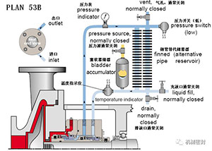
14. Flushing scheme
Scheme:
The external pipeline system provides isolation liquid for the external seal of the pressurized double face sealing device, and the reference pipeline from the seal chamber to the piston accumulator provides pressure to the circulation system. The flow is maintained by the internal infusion ring, and the heat in the circulation system is removed by the air cooling or water cooling heat exchanger.
reason:
Separation of process fluid, zero process discharge, higher pressure than 53A scheme. Dynamic tracking of system pressure
Occasion:
It is applied to double end pressure seal (double), high vapor pressure fluid, light hydrocarbon, dangerous/toxic fluid, heat transfer fluid,
maintain:
Before startup, all pipe networks are perforated, and no process pollution caused by plugging is below the reference line. The blocking fluid is compatible with the process fluid. The liquid level gauge of the accumulator will display the leakage of the inner and outer seals
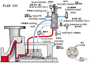
15. Flushing scheme
Scheme:
The external pressurized spacer tank or system provides clean liquid to the sealing chamber, and the circulation is completed by an external pump or pressure system. The pressure of the liquid tank is greater than the pressure of the sealed process medium,
reason:
Separation of process fluid, zero process discharge and sealing cannot promote circulation.
Occasion:
Applied to double end pressure seal (double), high vapor pressure fluid, light hydrocarbon, dangerous/toxic fluid, heat transfer fluid, dirty/corrosive or polymeric fluid, mixer/agitator
maintain:
Before startup, all pipe networks are perforated, and the circulating system is always pressurized or the barrier fluid is compatible with the process fluid. The liquid level indicator of the circulating system can display the leakage of the inner and outer seals.
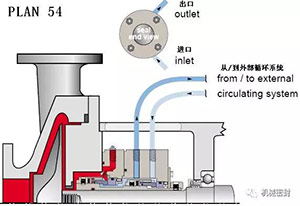
16. Flushing scheme
Scheme:
Quenching liquid is provided externally and cooled externally at the sealed air contact end. The cooling fluid is mainly steam, nitrogen and water
reason:
Prevent solids from accumulating at the atmospheric end of the mechanical seal, and use it together with the small clearance throttle bushing. Prevent icing.
Occasion:
For single end mechanical seal, oxidizing fluid, coke forming fluid, hot hydrocarbon, crystallization fluid, salting out fluid, lower than 32 ° F (0 ° C)
maintain:
The cooling inlet shall be at the top of the gland, and the outlet or drain shall be at the bottom. The cooling pressure shall be limited to 3 psi (0.2 bar), or a little lower. At the atmospheric end of the mechanical seal, the throttling pad shall be used to guide the cooling fluid to the seal drain, and the valve shall be monitored and checked frequently to see whether it is closed, whether the pipeline is blocked, and the condition of the steam water separation port.
17. Flushing scheme
Scheme:
The external drainage pipeline is arranged in such a way that the float level switch is used to measure the seal leakage and alarm the high leakage. The orifice plate at the downstream of the level switch is usually 5mm in diameter and is set on the riser leg. The mechanical seal is at the atmospheric end, and external drainage with leakage inspection is provided,
reason:
Used alone or together with Scheme 62, for throttling bushings with small clearance, for single end mechanical seals in external places,
Occasion:
Process leakage or leakage collection of cooling fluid, safety indicator of main seal.
maintain:
The water outlet is at the bottom of the gland, and the pipeline is inclined downward. Continue to drain water to the liquid recovery system. The flow limiting orifice (generally 1/4) at the downstream of the liquid level switch is vertical. It comes out of the bypass pipe from the overflow chamber and enters under the flow limiting orifice. When curing fluid is used, the pipeline may need to be heated. Frequently check whether the valve is closed, whether the pipeline is blocked, and whether the liquid level switch works normally.
18. Flushing scheme
Scheme:
Nitrogen is usually used as buffer gas for safety seal of gas control system of non pressure release device.
